Tiny Tapeout PLL
A CMOS PLL developed in about a week for a CPU project with my friend Ayan Ali using free Tiny Tapeout tiles we recieved at FOSSi Latch-up 2026.
One-week design sprint
We received free Tiny Tapeout tiles at FOSSi Latch-Up 2026 and had roughly one week to design something for them. Our goal was to explore how far we could push clock frequency within the available process and tile constraints.
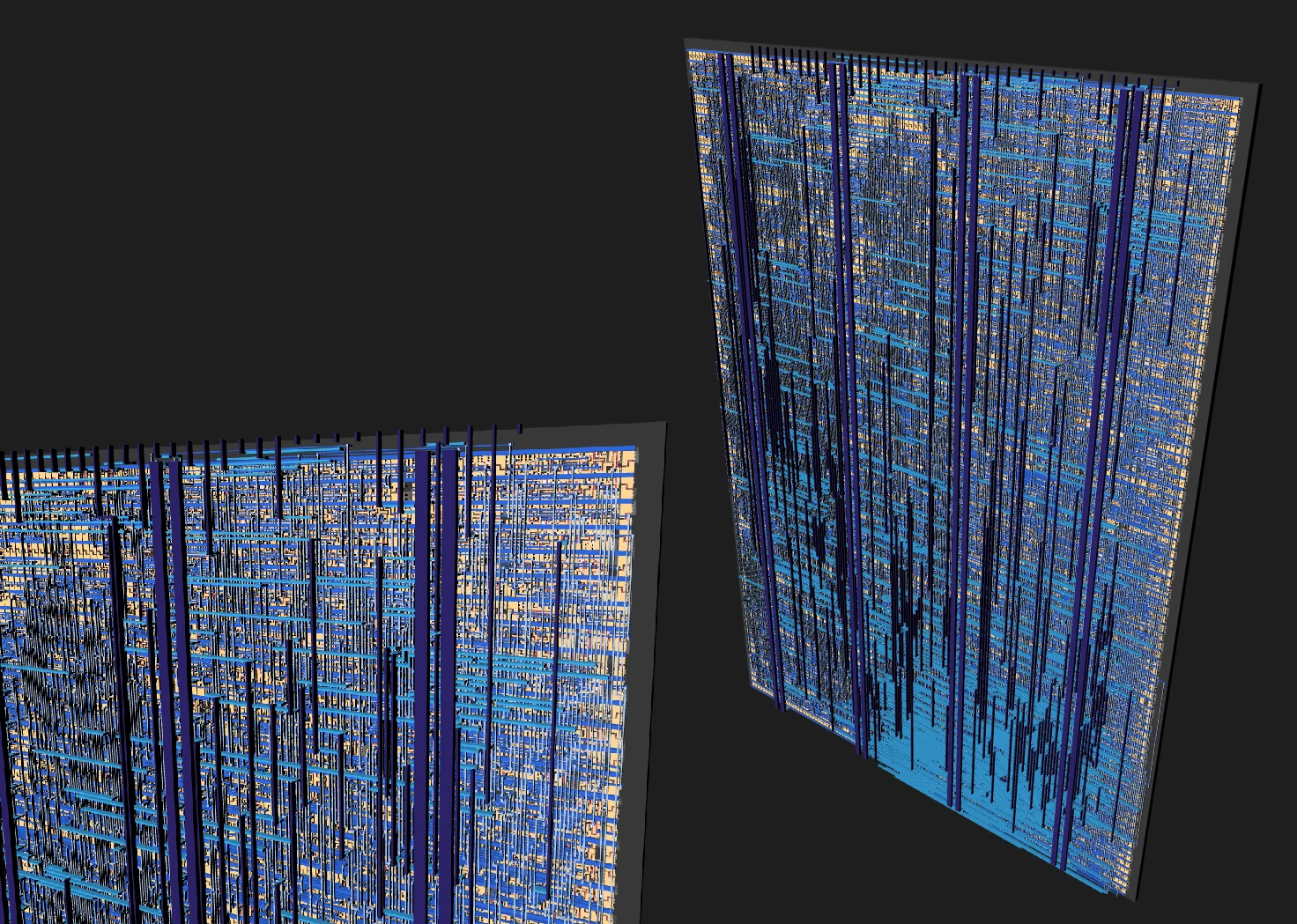
GDS Render of the final TT submission, without the PLL :(
Ring-oscillator exploration
I began with a ring oscillator in xschem and ngspice to establish what might be possible. The first test design simulated at almost 10 GHz.
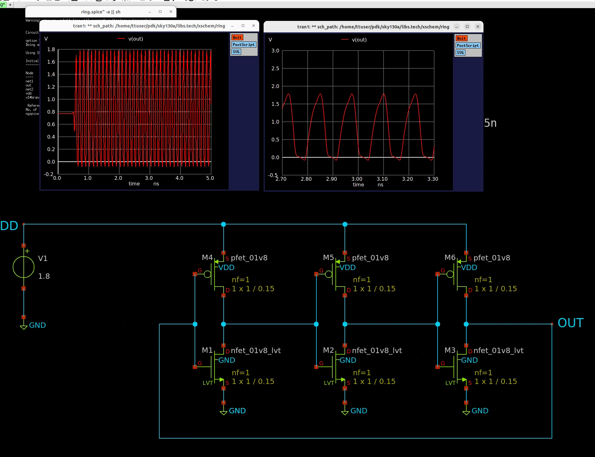
The first ring-oscillator feasibility test.
The next step was to add current starving to make it tunable, which also limited the max frequency to around 2 GHz.
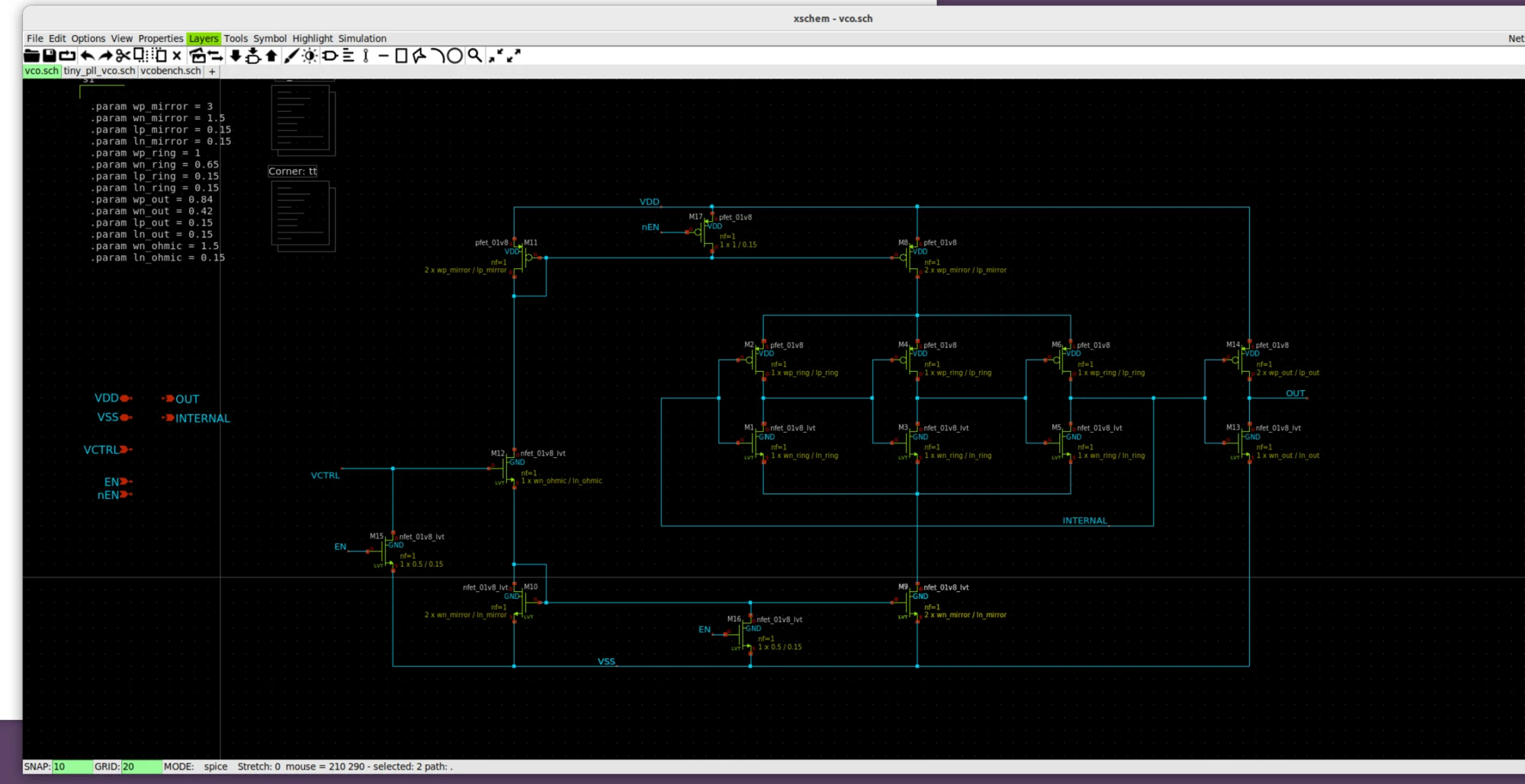
Ring-VCO schematic.
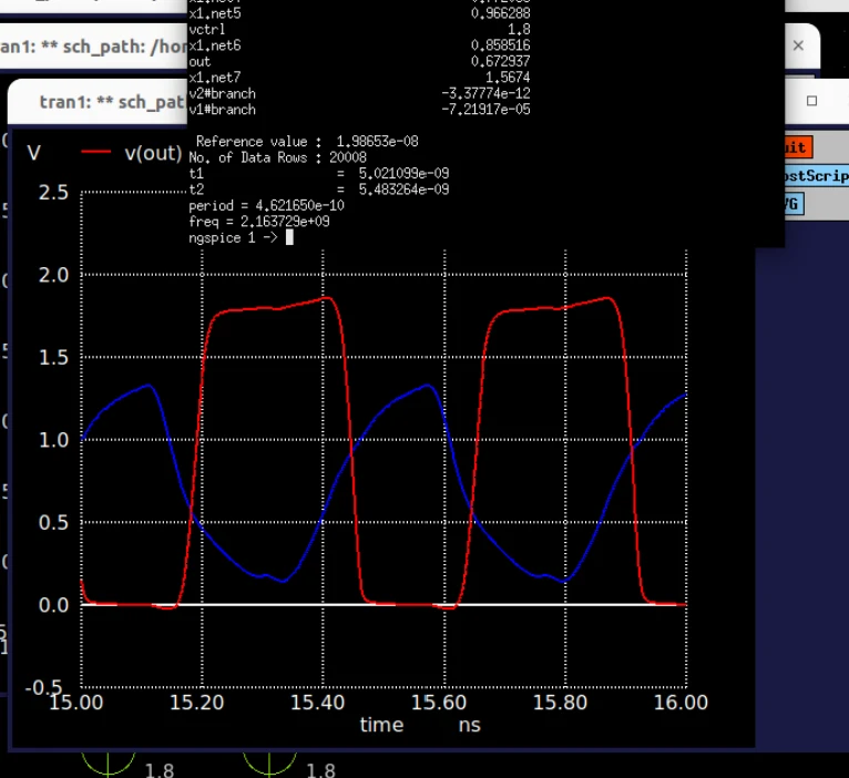
Maximum-frequency simulation for the ring VCO.
Loop filter and layout
As I was in a rush, I used some basic calculations in Excel to size the loop filter, then moved into physical layout and iterated on the block’s geometry.
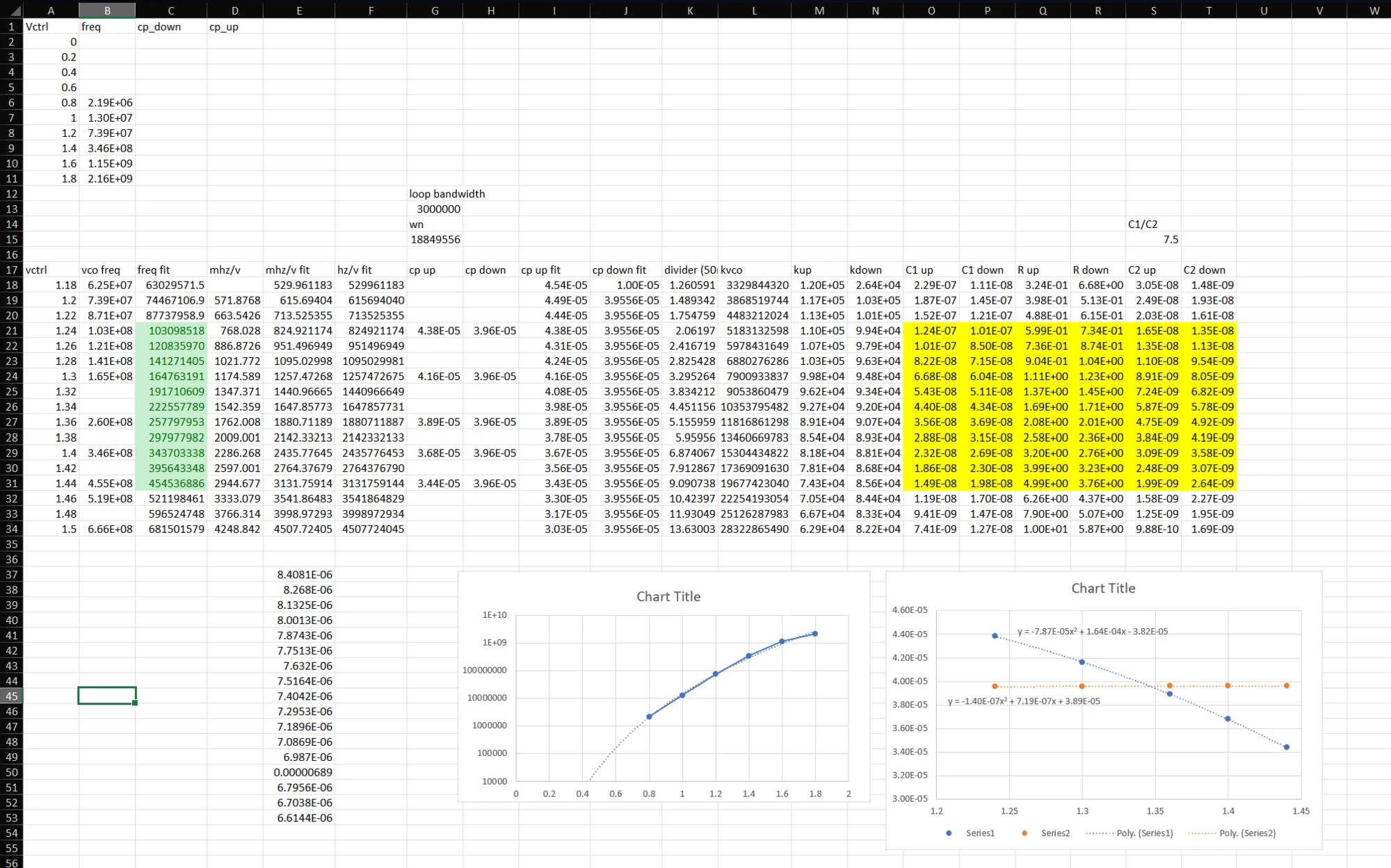
Loop-filter design calculations.
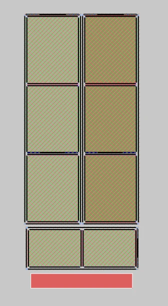
Beginning the loop-filter layout.
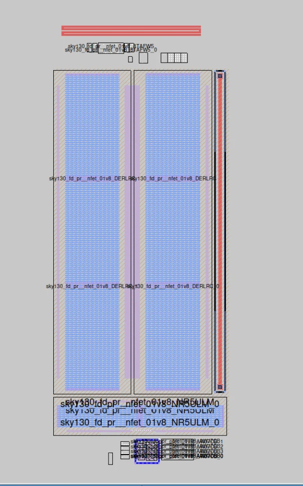
Layout in progress.
Integration decision
The completed PLL layout was brought to GDS and integrated into the CPU layout for evaluation. It was not included in the final submission: its utilization was high enough that the speed benefit was no longer practical for the available tile.
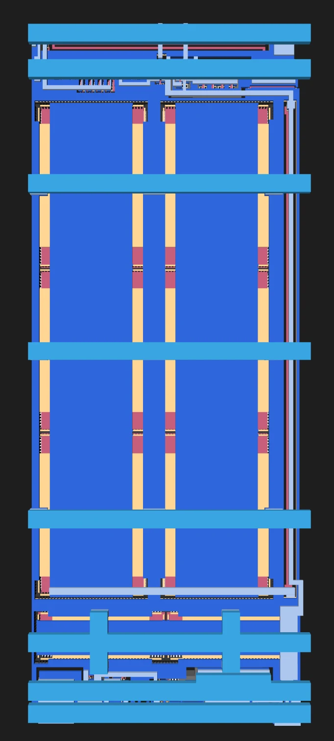
GDS view of the PLL.
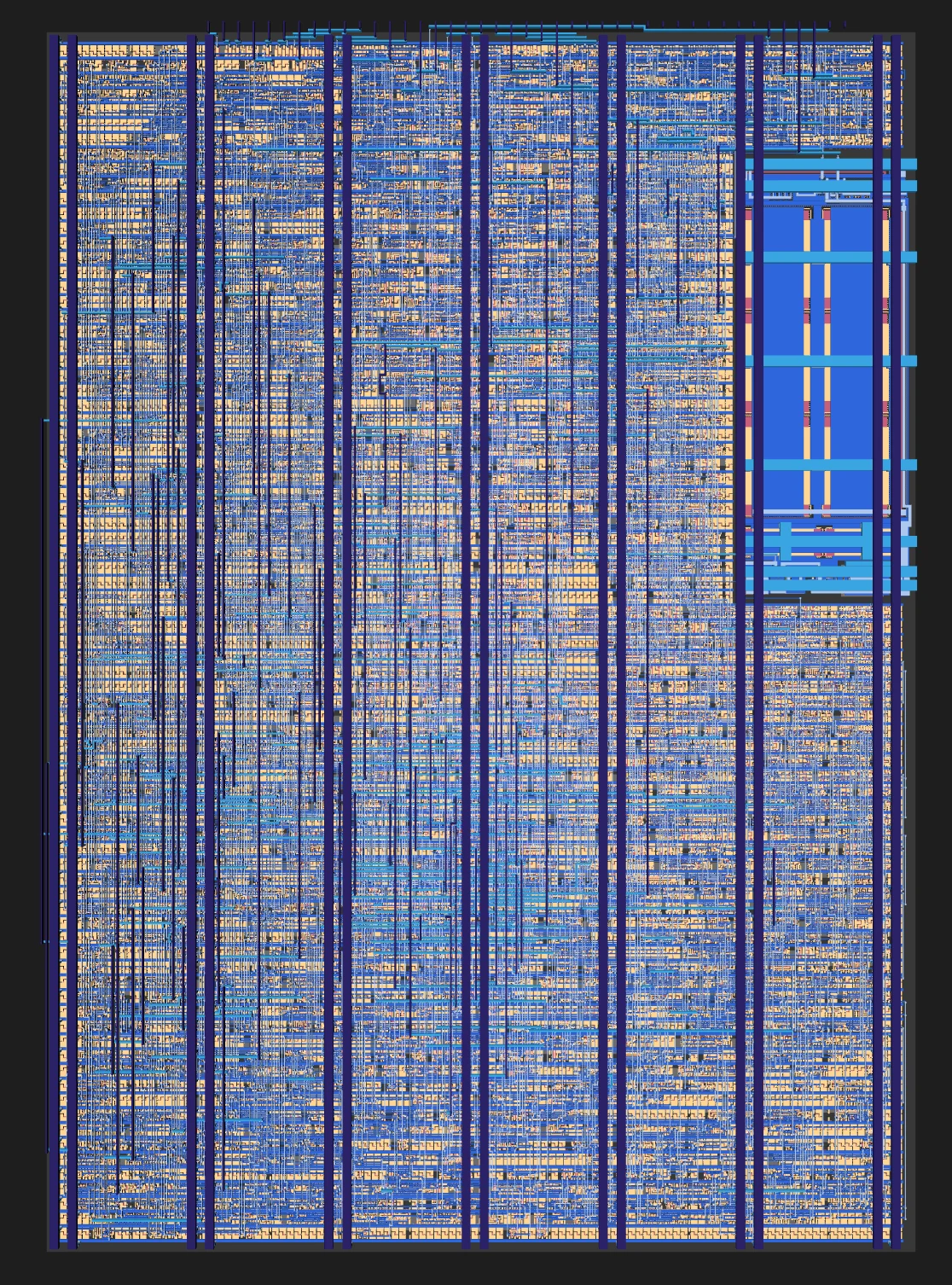
PLL integrated into the CPU layout during evaluation.