FINCH Cubesat Electrical Power System
An unregulated-bus power board using a COTS buck converter’s tracking input to obtain the input regulation needed for MPPT.
Architecture
This electrical power system uses an unregulated bus architecture. The MPPT function is built around a commercial buck-converter IC rather than a dedicated MPPT controller.
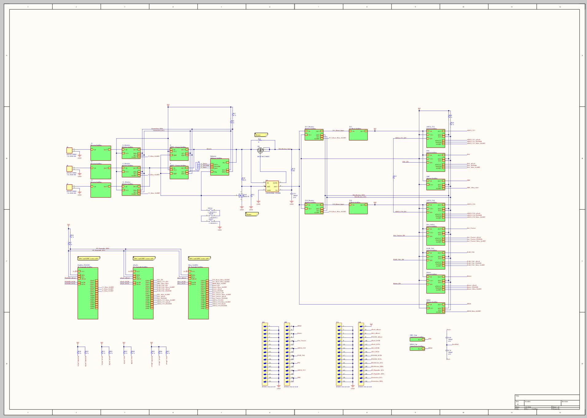
Top-level EPS schematic.
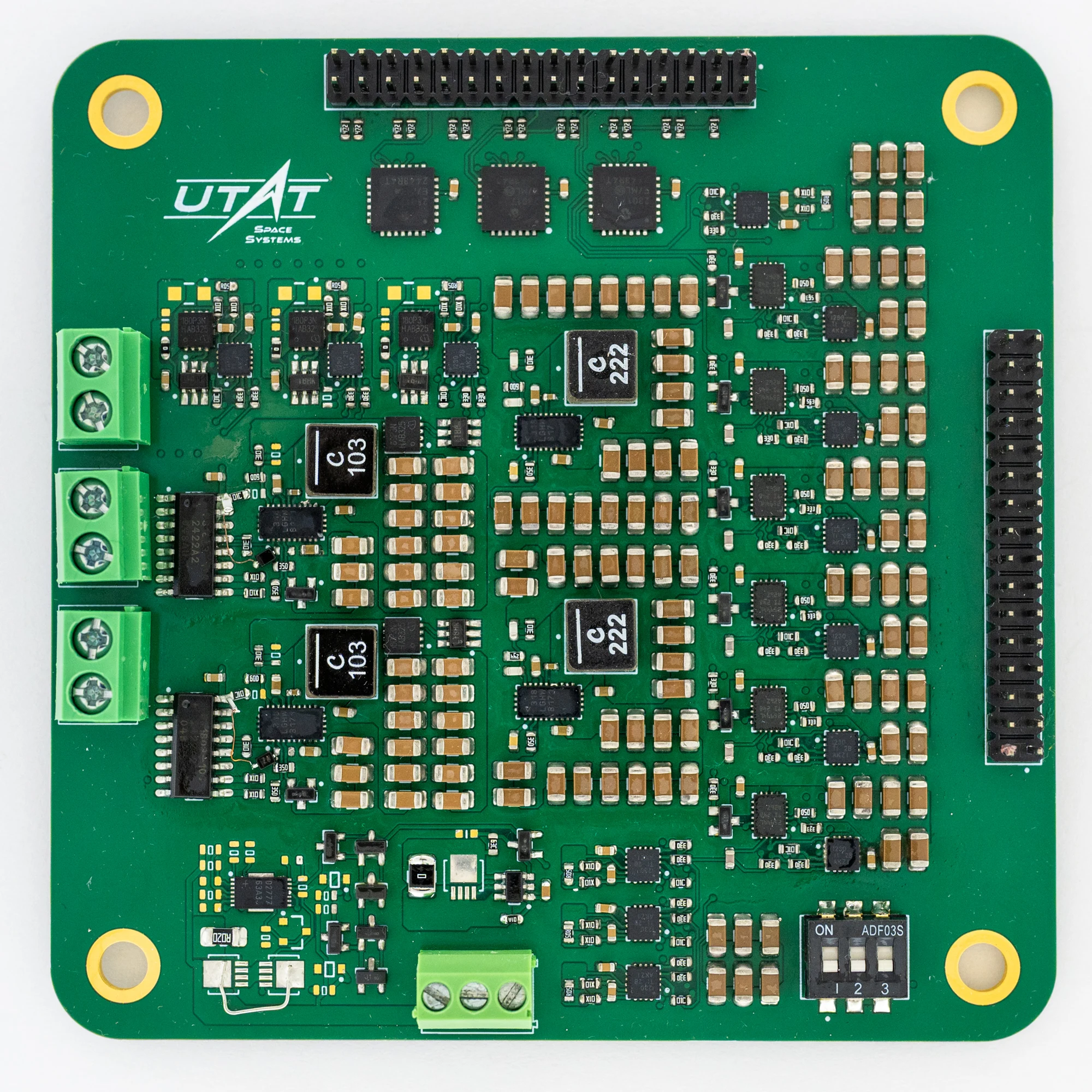
The completed electrical power-system board.
Input regulation
A normal tightly regulated converter presents negative incremental input resistance: as its input voltage falls, it draws more current to maintain output power. Connected directly to a limited source, that behavior can drive the input into collapse.
I used the buck converter’s soft-start and tracking input to produce the positive incremental behavior needed for input regulation. That let the converter regulate the source operating point for MPPT while still using an off-the-shelf power stage.
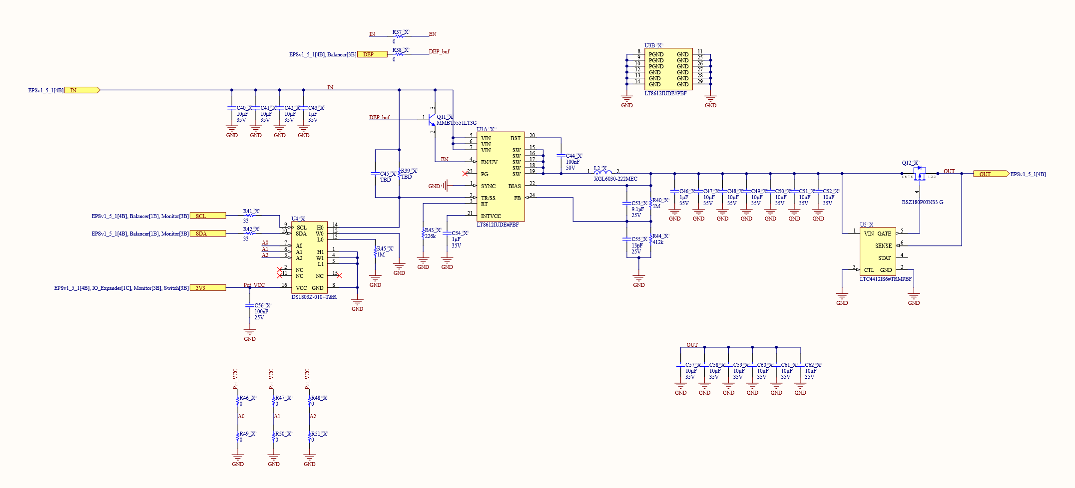
MPPT converter schematic.
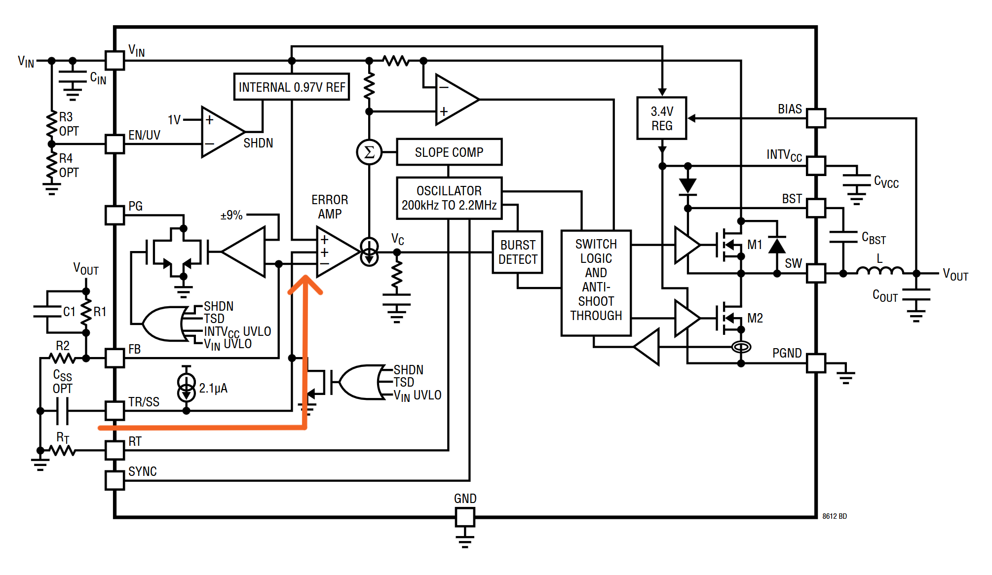
Internal block diagram of the LT8612 Buck IC I used, signal path for input regulation shown by the orange arrow. Credit Analog Devices
When the battery voltage hasn’t topped out, the SS/TR pin is regulated to the voltage at the FB pin, meaning the maximum power point can be set by a divider.
PCB design
The board was captured and laid out in Altium, combining the converter channels, control circuitry, and board-level interfaces on one assembly.
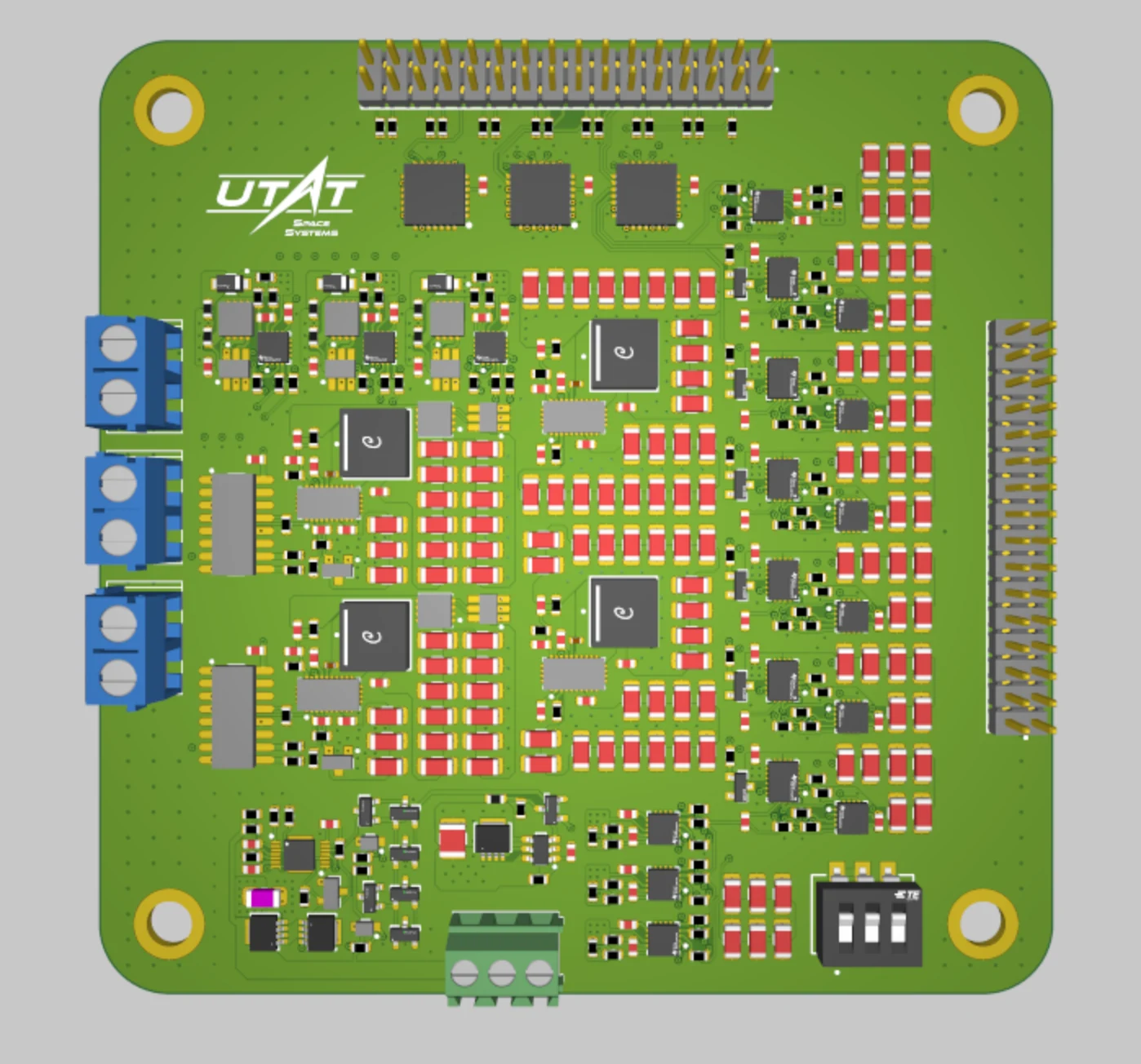
The board layout in Altium.
Open the EPS PCB layer plots in a new tab
Since parts of the satellite design hadn’t been finalized yet, I simplified some parts of the board like the inhibit and connectors to allow for easier testing.