High-Voltage Electrostatic Headphone Amplifier
A high-voltage amplifier PCB designed to drive electrostatic headphones, with repeated analog stages and onboard power circuitry.
Overview
This project is a high-voltage amplifier designed to drive electrostatic headphones. The PCB brings the repeated analog amplifier stages together with the supporting power and control circuitry on a single board.
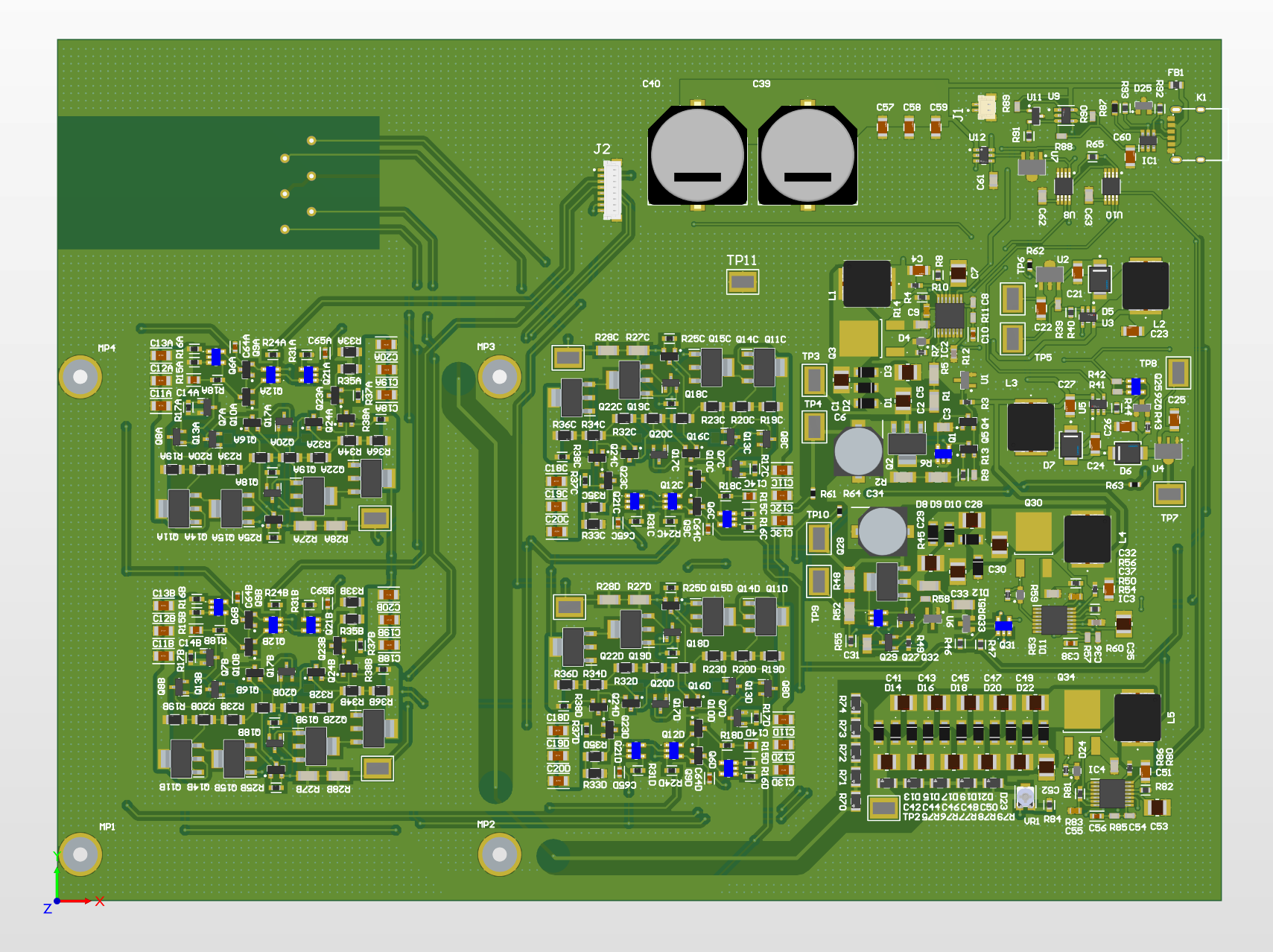
The assembled-board rendering used during PCB layout.
Revision 1 amplifier topology
Electrostatic headphones require roughly 1000-1600 Vpp of differential swing, or about 500-800 Vpp from each amplifier half. Unfortunately, the very limited availability of high voltage complementary transistors (which were mostly used for CRTs) is very limited, so some creativity needs to be used to make an amplifier.
Revision 1 used a custom three-stage amplifier with bootstrapped amplification and output stages. Splitting each stage across device pairs allowed transistors rated for approximately half of the total high-voltage rail span to be used.

Simplified bootstrapped output-stage concept.

Revision 1 bootstrapped Class AB amplifier topology.
The main features were:
- A cascoded input stage to reduce input capacitance and protect the input transistors from the high-voltage rails. Because the signal remains in current mode before the current mirror, the cascodes provide protection rather than additional voltage gain.
- Bootstrapped voltage-amplification and output-buffer stages.
- Output-current limiting and conventional Miller compensation.
- Class AB biasing with diode-connected transistors to track the higher base-emitter voltage of the high-voltage BJTs.
Although this topology provides a lot of benefits for high voltage, it does have some interesting limitations, like a comparatively very narrow input common mode range, which is limited to the low voltage supplies.
Build progress
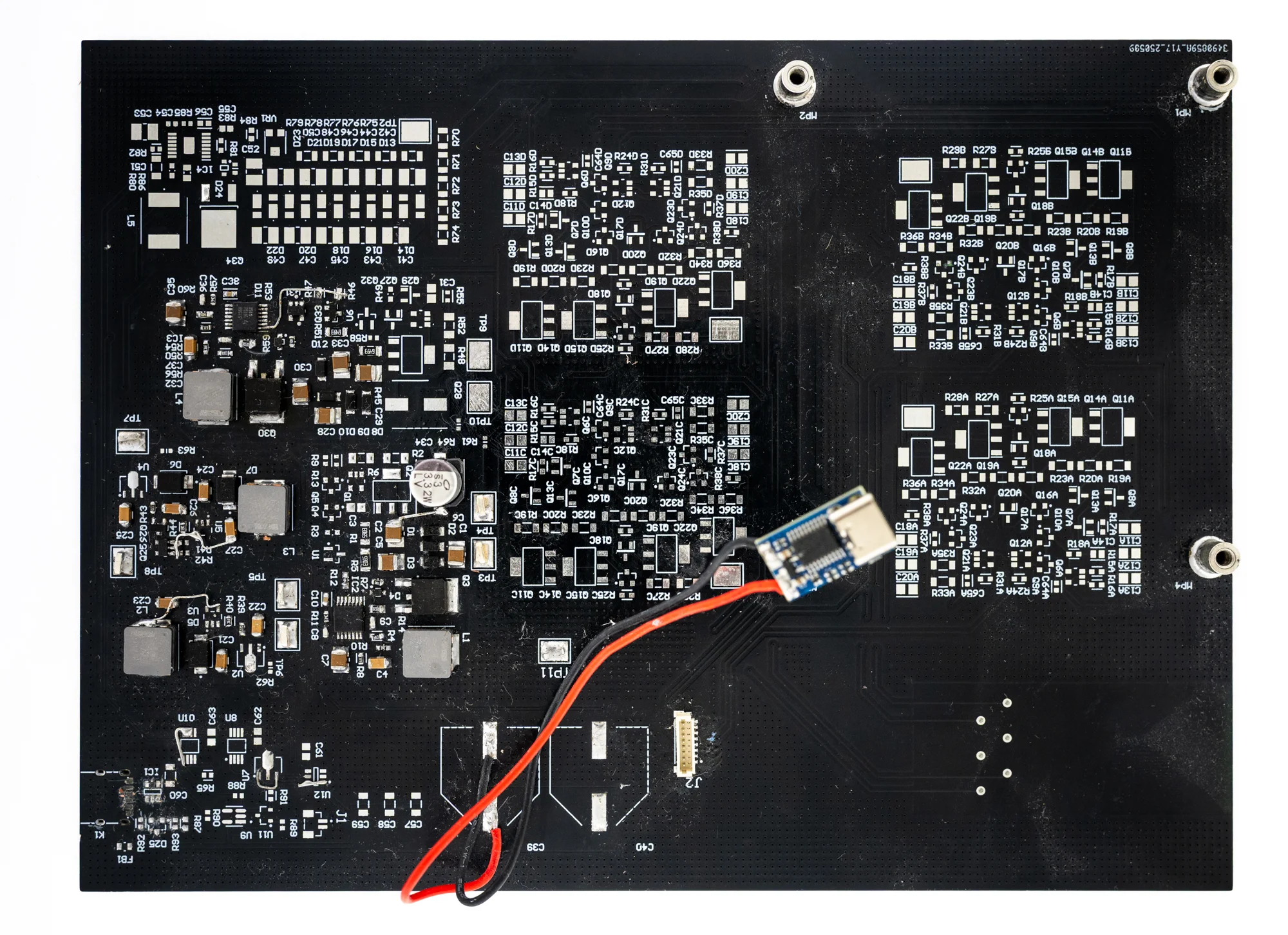
Main PCB during assembly.
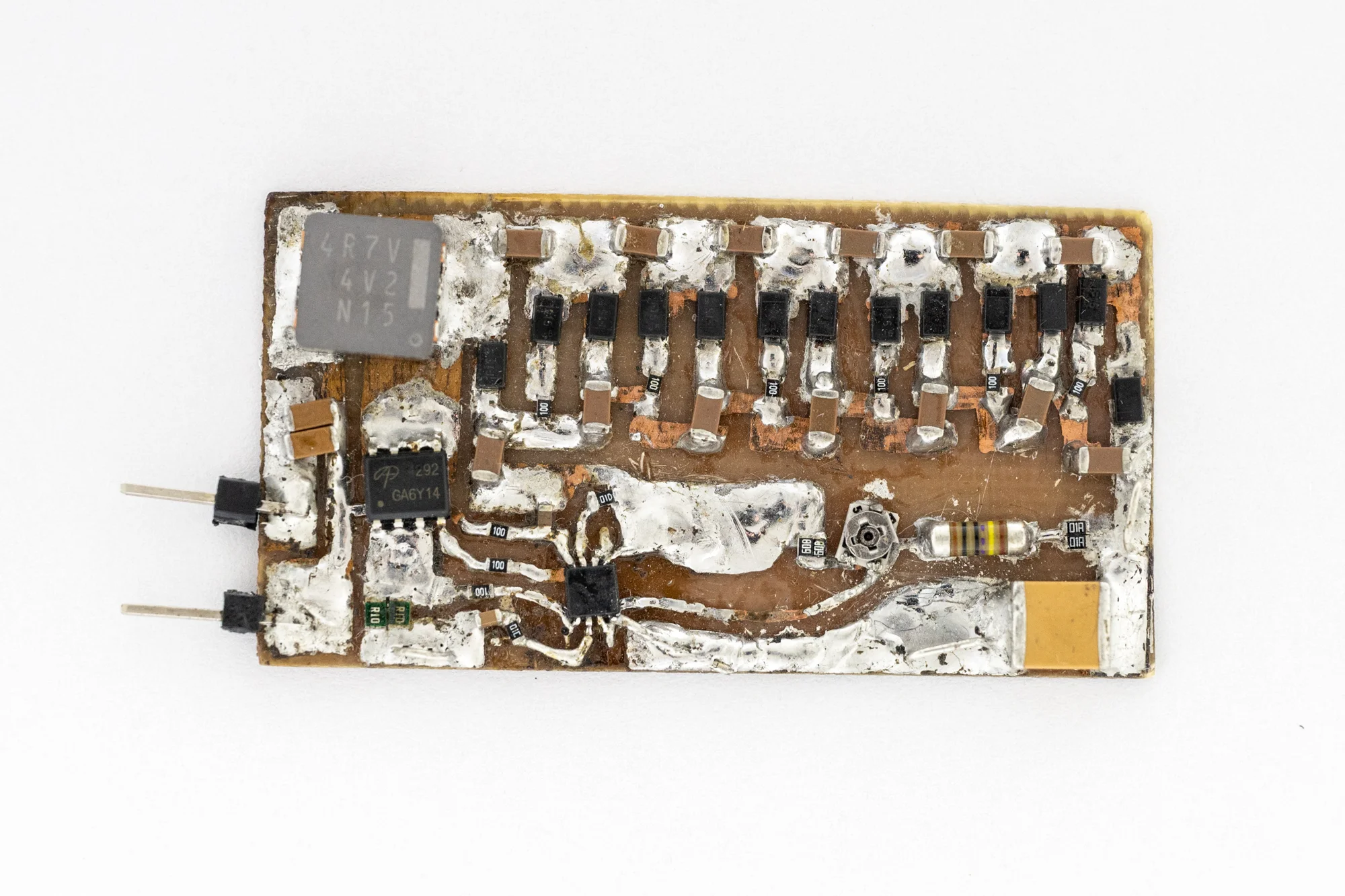
High-voltage boost converter prototype.
600 V boost-converter prototype
I tested the boost-converter prototype at 600 V to check its startup behavior and thermal performance.
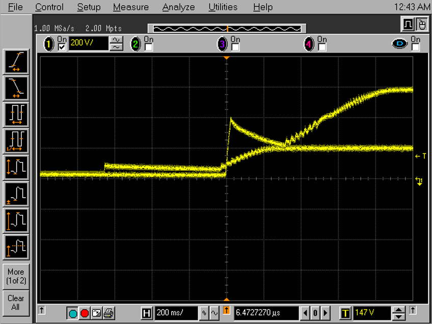
Startup behavior during 600 V testing. The two traces are because of a persistence thing on the scope.
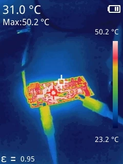
Thermal image during the test; the measured maximum was 50.2 °C.
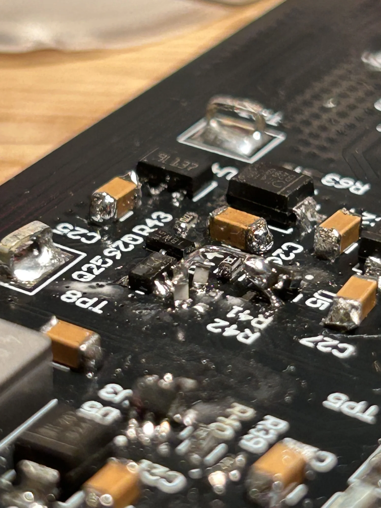
Board rework in progress.
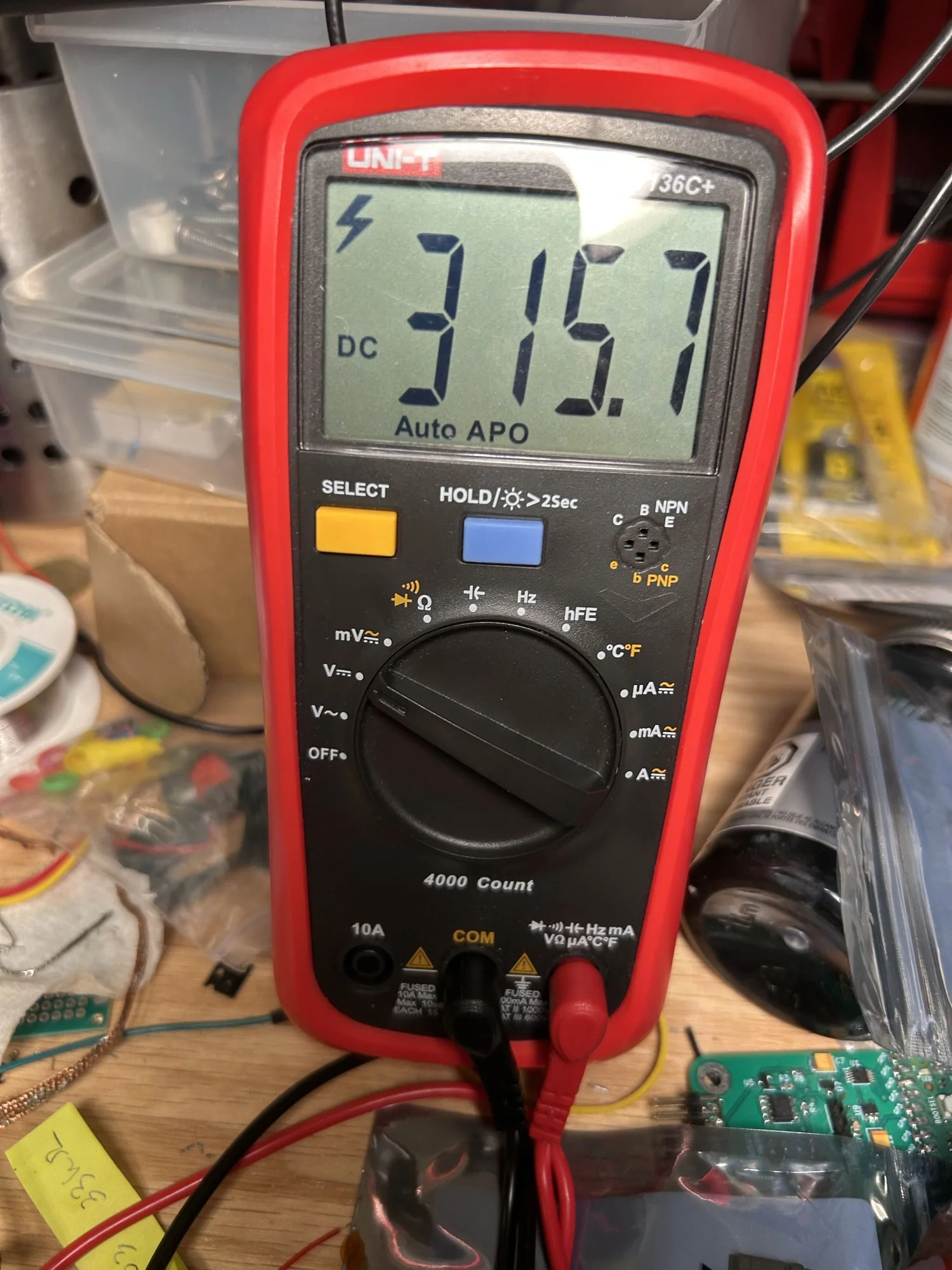
Power-supply bench measurement.
Revision 2
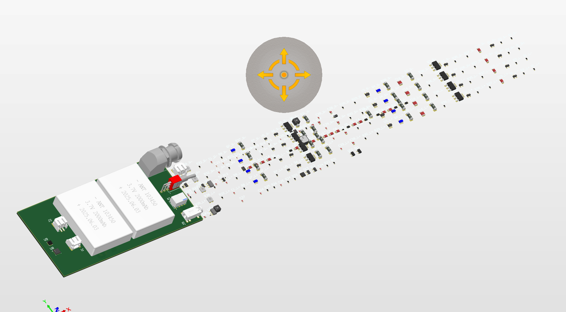
Revision 2 PCB rendering.